In the field of electrical engineering, a power system is made up of several pieces of equipment and one of them is a transformer which is the most crucial part of the whole system, the same as a heart in the human body. The main objective of a transformer is to change the voltage levels as per requirements using the electromagnetic induction. A step-up transformer is widely used in the power transmission system to transmit electricity to a longer distance with maximum efficiency, whereas, a step-down transformer mainly used in the distribution system to cater the consumer’s requirements.
There are different types of transformers which are being used in the electrical system and one of them is “Autotransformer” which consist of a single winding unlike conventional transformers which acts as both primary as well as secondary. Also, this type of transformer is available in both single phase and 3 phase configuration. In this article we will study briefly about the 3 phase autotransformer but at first it is important to take a look at how an autotransformer works.

Working Principle of an Autotransformer:
The construction of an autotransformer is consist of a single winding (Figure 1) that works similar to conventional transformer based on Faraday’s 1st law of electromagnetic induction, which describes as “whenever a conductor is placed in a varying magnetic field, an electromotive force (EMF) is induced. If the conductor circuit is closed, a current is induced which is called induced current”. Now, when alternating current is applied to the primary winding of the autotransformer, then an EMF is induced in the primary part according to above said law (Popovic, 2006).
As the conductor is stationary, whereas the magnetic field is alternating in nature, as a result a flux is produced in the primary part by the induced EMF and that is called primary winding magnetic flux. As soon as this magnetic flux is associated with the secondary winding of the autotransformer, an EMF is induced in the secondary winding through mutual induction. The magnitude of induced EMF is calculated on the basis of the number of turns of secondary winding. Here is a generalised equation of ratio between both primary winding emf and secondary winding EMF.
E1/E2= N1/N2=k
In this equation E1 and E2 are the induced EMFs, N1 and N2 are the number of turns of primary and secondary windings respectively. Whereas, “k” represents the transformer turns ratio. This equation clearly shows a directly proportional relationship between magnitude of induced EMF and number of winding turns. Hence, greater number of turns of secondary winding represents a step-up autotransformer. While a step-down autotransformer has less turns of secondary winding. Furthermore, in conventional two winding transformers, the core is the main source of flux linkage between primary and secondary winding without any electrical link. Therefore, a transformer is called a magnetically coupled machine. However, an autotransformer is called both electrically and magnetically coupled device due to single winding (Ziomek, 2018).

Fundamentals of 3 phase Autotransformer:
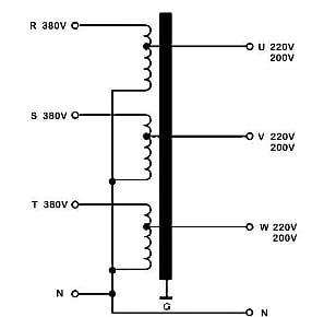
Above mentioned theory reflects the concept of single phase autotransformer which is the basis of 3 phase autotransformer as well. For this purpose, three single phase autotransformers can be used to build a single unit 3 phase autotransformer. The figure 2 shows the star-star connection of said autotransformer. In case of delta-delta connections, then there will exist phase difference between primary and secondary windings which is actually not desired (Prasad, 2019). On the other hand, an additional delta connected winding is used with 3 phase star-star connected autotransformer to manage zero sequence currents as well as third harmonic currents (for imbalanced systems).
This is the general approach for the step down case which is described and it is noted that single phase and 3 phase autotransformers are more suitable for step down applications. However, by interchanging the position of source and load, the step up scenario can easily be analysed. For this purpose, the directions of primary and secondary currents are reversed. It is important that to maintain MMF balance, the current direction in series winding is linked with change of current direction in common winding (Prasad, 2019).
Applications of a 3 phase Autotransformer:
These autotransformers are mainly utilised in different systems, i.e. electrical power transmission and distribution, induction motors, audio systems, and railway systems. In the high-voltage power grid, the 3-phase autotransformer is one of the most significant equipment to ensure the secure and dependable functioning of the power grid and continuous distribution of electrical energy. Whenever the distribution lines experience a voltage drop, the 3 phase autotransformers are used to rectify this drop (Ziomek, 2018).
Furthermore, this autotransformer plays a salient role in starting of an induction motor and synchronous motors, because these motors take higher current at starting due to which the voltage drops. Thus, a 3 phase autotransformer enhances the voltage when the motor is switched on. Also, they supply required voltage to the furnaces to operate.
3 phase Autotransformer, Advantages and Disadvantages:
Every kind of transformer has its own positives and negatives. So it is necessary to be aware of these for a better selection. Here are some advantages and disadvantages of 3 phase autotransformer;
Advantages:
Comparatively cheaper than a two winding transformer.
More efficient due to low copper losses even if the rating increases.
Lower exciting current.
Greater voltage regulation because of the less leakage flux.
Disadvantages:
Having Larger short-circuit current.
Not secure to be used for stepping down high voltage for a smaller load due to the absence of isolation between primary and secondary windings. Thus, only convenient for adequately smaller voltage conversion.
The 3 phase autotransformer mostly works as a source of ground fault currents as it is not very effective in conquering harmonic currents.
Conclusion:
The above study concludes that 3 phase autotransformer is a suitable choice due to low copper losses, high efficiency and greater voltage regulation. Although the principle function of different types of transformer is the same, this specific type is more advantageous and cheaper due to its compact design and simple construction. However, it is necessary to get significant knowledge about the application and pros and cons of 3 phase autotransformer to get maximum satisfactory results.
This article is generated and published by FPJ focus team. You can get in touch with them on fpjfocus@fpj.co.in